

Fitting Jenvey throttle bodies to Elise/Caterham
First
off its important to understand that the throttle bodies do not just ‘bolt-on’,
there are a number of modifications and steps to be taken to ensure that the TBs fit
properly, work properly and give a trouble free service life.
The
first step is to drain the coolant and remove the inlet plenum from the head, this will
involve disconnecting the fuel rail from the fuel supply, the injector harness from its
loom connection, the throttle position sensor from its loom connection , the IACV from its
connection, the throttle cable from the quadrant and the breather pipes from the
connections to the plenum and the air temperature sender. You will also need to disconnect
the water bleed from the spout on the far end of the plenum.
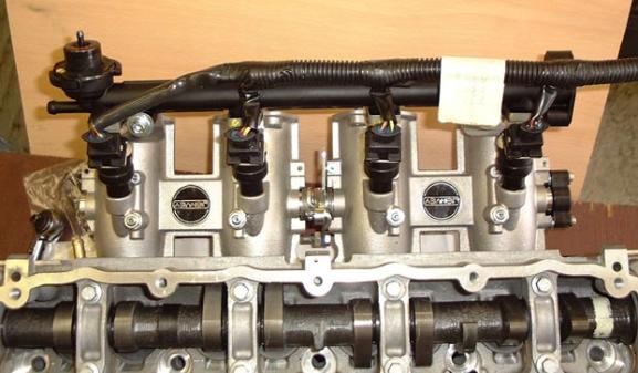
Following
removal of the plenum if you find that the inlet side of the head has studs which are
permanently fixed into the head you must remove all these studs. Remove the throttle
position sensor from the plenum and retain, remove the air temperature sender which is
screwed into runner number four, also remove the fuel rail and injectors from the plenum.
If your plenum is the VVC type then it will need to be split into it’s two halves to
facilitate removal of the fuel rail. Remove the fuel return pipe from the plenum and leave
attached to the car. Remove the air temperature sensor which screws into number 4 runner.
Before
the TBs can be fitted there are a few modifications that need to be done to the bodies of
the TBs themselves.
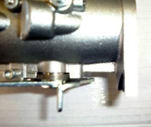
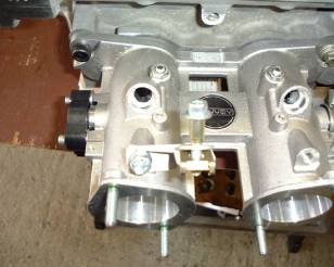
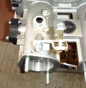
i)
The linkage connection bar on the rearmost TB needs bending in order for it to work
properly, if this is not done then there is a real danger of the TBs sticking in the fully
open position, the photographs below show before and after the modification.
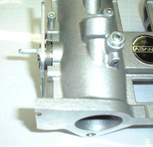
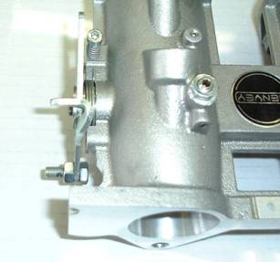
As
you can see the connecting bar n the linkage has been bent over at the top by around
4-5mm.
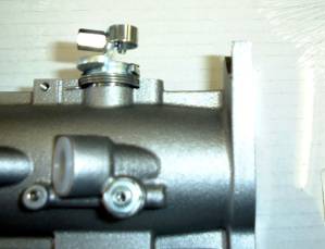
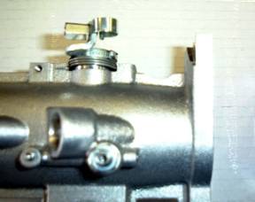
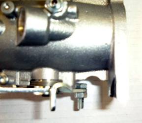
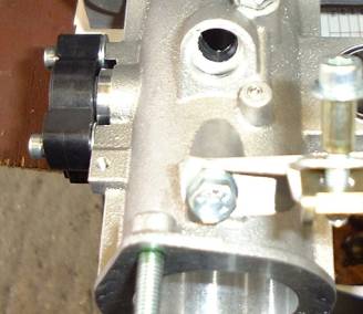
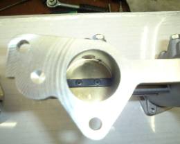
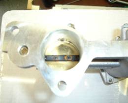
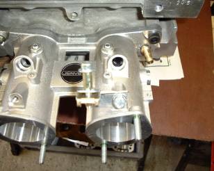
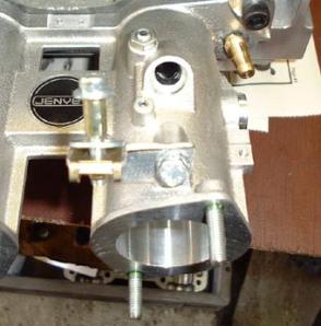
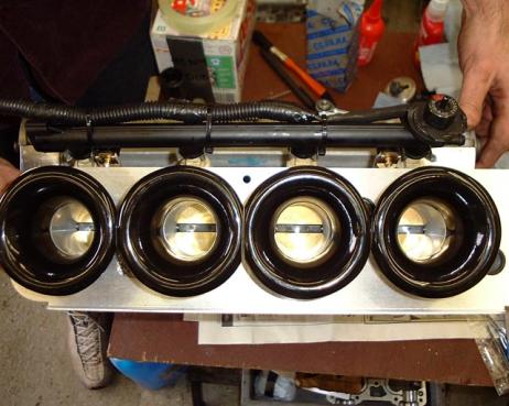
ii)
Clearance needs to be made for the throttle trunnion between the two TBs, this is a safety
modification to ensure that the throttle cannot stick open, a small part of the webbing on
the inner side of each TB is removed to give extra clearance around the drop arm/trunnion
as shown below. The rearmost TB is modified on a similar fashion as the mirror opposite,
note that the rearmost TB picture shows the throttle trunnion fitted.
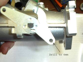
iii)
The linkage drop arm needs to be drilled to 6mm and the hole deburred in order to allow
fitment of a throttle trunnion
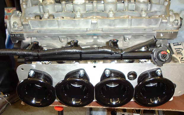
iv)
The front TB needs modifying and drilling/tapping to accept the water spout for the bleed
hose to the header tank. A fair bit of material needs removing from the flange of the
front TB around the are of the spout drilling and the redundant mounting on the side of
the front runner. Make sure that you are modifying the correct TB. The hole for the spout
can then bedrilled from the inside face of the manifold flange at and angle of 20 degrees
to the vertical and horizontal so that the spout will point up and away from the runner.
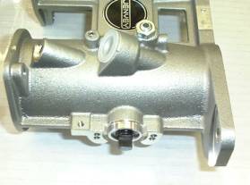
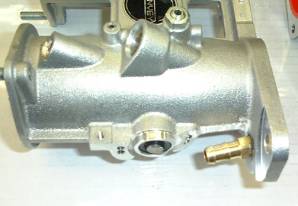
The
hole for the spout needs to be around 9 to 9.5mm in size and slightly tapered. The spout can easily cut its own thread although
an M10 tap can be used to cut the first couple of threads to ease fitting. The spout
should be fitted with Loctite 648 or similar stud retainer, alternatively a heat resistant
epoxy could be used. Note that the redundant end of the throttle shaft is removed to make
access to the spout easier.
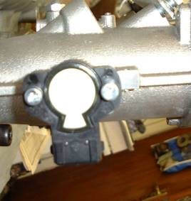
v)
The throttle position sensor should be attached to the rearmost TB mounting, the screws to
fit the TPS are usually too long and will bottom in the holes, check that this is true and
of so shorten them a little (usually 6mm) so that they can successfully hold the TPS. The
TPS will fail in service if it is bolted straight to the end of he shaft, it is necessary
to use an M6 washer between the TPS and the TB body at each bolt hole to prevent the TPS
binding.
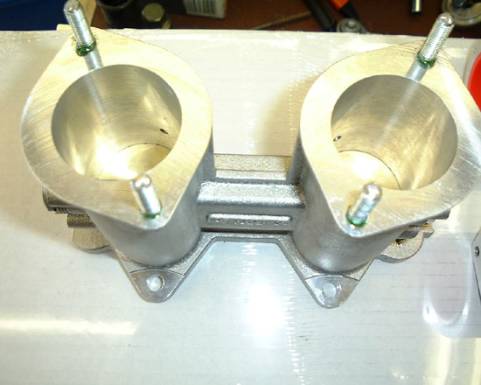
vi)
The studs provided for mounting the airhorns must
be locked into the rear flanges of the TBs with either Loctite 648 or quick setting epoxy.
If this is not done the nyloc nuts provided with the airhorns may not lock properly and
may come loose, if these come away from the studs then there is a good chance they will
enter your engine and cause severe damage.
vii)
The TBS should then be matched to the cylinder head inlet ports as best you can. If you
attach each TB in turn to the head and then peer down the barrel you should be able to see
if the inlet port overlaps the TB in any position. If so it is possible to modify the
inlet port entry if you carefully pack the port with wadding and then remove the packing
and debris after the work is done, preferably using a vacuum cleaner. Ensure that the
inlet valves on the cylinder being modified are closed and that the remainder of the
engine is suitably masked. If the inlet ports are larger than the TB entry then the TB
entry can be enlarged to suit. A paper or cardboard pattern can be made to help with this
or the inlet flange can be smeared with MS (dark grease) and the TB pressed up hard
against it.This should leave an impression of the port entry on the TB flange. Make sure
that any metal removal is blended carefully with the rest of the port.TB runner so that
the change in shape is gradual as possible.
The
TBs cannot be attached using the original studs and nuts or original flange bolts (if
fitted), They need to be fitted using M8 x 25 socket
head capscrews on the underside. The two outer upper holes can also use M8 x 25mm
capscrews, or if preferred the original studs can be retained to help locate the TBs when
fitting but these should be shortened by approximately 10mm to give space. The centre top
hole should use another M8 x 25 capscrew or M8 x 25 flange bolt
When
fitting the TBs use the gasket provided, or if one is not provided use a VVC inlet
manifold gasket, do not use an old 1.4 paper
gasket. It is advisable to use a little sealant between the water ways and the adjacent
cylinder runners on cylinders 1 and 4.
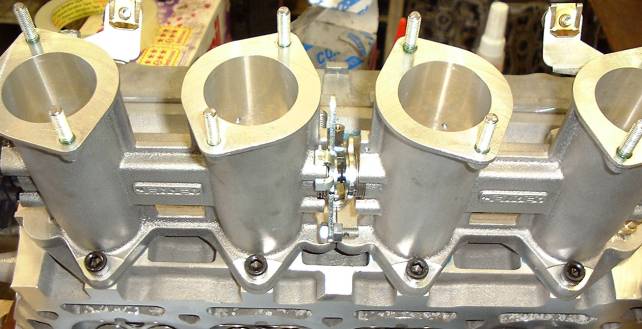
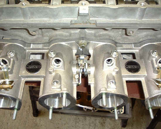
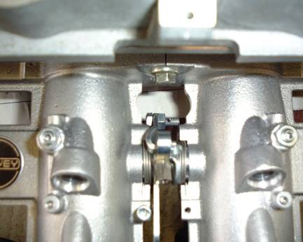
Make
sure that the linkage is put together as shown in the photograph below with the clip on
the front TB firmly around the transfer bar on the rear TB.
Show
how to Make throttle trunnion from bolt.
On
Caterham fit fuel rail mounting brackets as shown
Swivel
injectors so that the connectors face up
Re-attach
fuel rail loom and cable tie to fuel rail
Attach
fuel rail and injectors, light smear o WD40 on O rings
Bolt
fuel rail to brackets
Fuel
rail supply pipe to be turned thru 180 degrees so it points away from the airbox
cut
nipple off cable and connect.
Attach
cable and lock onto trunnion so that trunnion is still able to turn on drop arm
Attach
air temp sensor to backplate, either retap thread to M10 and use M10 nut, or use M10 nut
cut in half and lock on. Make sure nut loctited
Shorten
engine breather pipe and mount from breather to hole in backplate, taper rubber slightly
to fit hole.
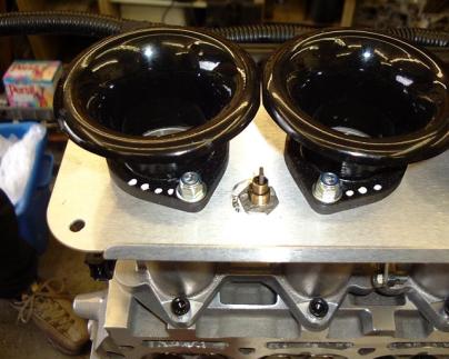
Attach
backplate and wire in air temp sensor, attach airhorns with washers and lock nuts.
Don’t
fit airbox until TBs are set and balanced
Attach
airbox with loctite on bolts.
Setting up TBs for balanced running
Close
the TBs completely and then adjust the balance mechanism so that both start to open at
*exactly* the same time. open the throttle fully to make sure that all 4 plates are at the
same angle when fully open to confirm they are in balance, it's often easier to see
discrepancies when the throttle is fully open.
When
they are balanced by eye, open the throttle on the adjustment screw by a small amount.
Align the throttle pot using the M3D software.
Start
the engine and get to normal running temperature, if it wont start increase the throttle
opening a little and re-align the throttle pot.
Then
use the following procedure to set up the idle and corectly align the pot/map. It's been
developed over many many sets of TBs and works.
Note
when setting the idle and balance *do not* under *any circumstances* play with the air
bleeds to achieve idle, these *must* be in the fully closed position regardless of the
type of linkage in use. These are for minor trimming between barrels when the balance
between the two throttles on a single DTH TB is out and when the overall balance between
the two TBs is as near as you can achieve using the balance mech. If you use the air
bleeds to set the idle then the moment the throttle is opened the balance will got to hell
in a hand basket and progression will be downright awful, you *MUST* balance the throttle
plates and idle is the only place you can practically measure the airflow and achieve
balance.
First..
Turn
off idle control in the software!!!!
Make
sure the engine is hot
Make
sure the idle advance is no more than 5 degrees,
Slacken
the locking nut on the balance mech
Then..
i)
make sure there is some slack in the cable.
ii)
measure the airflow between TB 1 & 2 against TB 3 & 4.
iii)
if 1 & 2 are low, increase by turning the balance grubscrew clockwise, if 1 & 2
are high reduce by turning counter clockwise. If they balanced lock up the adjustment
grubscrew and ensure you have 1000RPM, if they are balanced and at 1000RPM go to viii)
iv)
adjust the overall idle adjustment screw if idle falls or rises too much, set idle to
1000RPM
vi)
if you have adjusted the overall idle adjustment screw then make sure you re-align the
throttle pot in the software immediately.
vii)
go to i)
viii)
Let the engine idle and go to the live adjustments screen
Look
at the lambda scale and adjust the fuelling until it shows two or three bars into the
yellow, try trimming the fuel up and down two or three points and note the point at which
the idle starts to fall in either direction, then go for the middle point which should
give a clean and reasonable idle. If the idle starts to fall when you are adjusting the
fuelling *then you are going in the wrong direction*, start adjusting in the opposite
direction, The fuelling is right generally when the idle is at its fastest, if the Lambda
scale doesnt appear or appears way off then it could be that your sensor is faulty. If the
idle speeds up , adjust using the idle adjustment screw *NOT* the fuelling or timing,
reset the throttle pot each time you adjust the idle screw. Recheck the balance.
When
you have the idle stable and smooth at 1000RPM and the lambda reading consistently in the
yellow by 2-3 bars then the idle is OK. Reset the throttle pot and set idle control on in
the software with values of 25 degrees and an update rate of 10, then all should be well.
It
might take a while to go round the cycle a few times, be patient, take your time, its
worth the effort.
If
you dont have a near perfect idle then you have not followed the above, I have never known
it to fail.