

The standard cam sprockets on the K series come with alignment markings and specific dowel positions for the inlet and exhaust cams which allow error free assembly and initial cam timing. Vernier timing wheels such as those supplied by Piper are not 'handed' in this respect, both verniers are identical and they do not have alignment markings. This can make the initial timing of the cams when first fitting verniers a bit of a problem.
Before
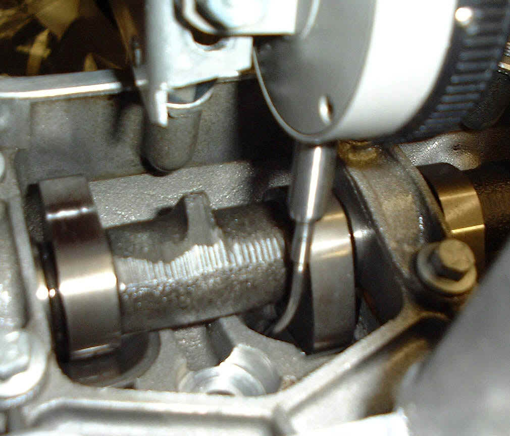
removing the old sprockets it is wise to turn the engine to 90 BTDC until the timing marks
line up as per the picture below.
A
foolproof way of ensuring that the cams are initially correctly timed with the verniers is
to transfer the timing marks from the old cam sprockets to the verniers in the correct
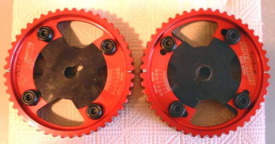
position. The first step is to designate one of the vernier pulleys as an inlet and the
other as an exhaust and then mark the pulleys accordingly.
Following this the horizontal marks on each original pulley can be transferred by laying the original pulley over the new vernier and aligning the appropriate dowel slot on the old pulley with the dowel slot on the new one, the picture below shows the alignment markings transferred onto the verniers from the original sprockets with the verniers aligned how they should be for fitment to the engine when the engine is at 90 degrees BTDC (before top dead centre). Note the arrows on the original sprockets which are marked as 'exhaust' are represented by a second scribed line on the verniers forming a simple arrowhead.
Before
fitting it is wise to advance the exhaust vernier by 10 degrees and retard the inlet
vernier by 10 degrees, this lowers the lift at TDC and therefore makes the cam timing very
safe prior to fitment and final setting.
Setting
the cam timing using 'lift at TDC' method
By far the best way of establishing the correct cam timing is to measure and set the valve
lift at Top Dead Centre on the non firing stroke. The lift at TDC for each of the cams in
the Piper range is given on the Piper page, note
that this may be different for the inlet and exhaust cams of a pair. Once your verniers
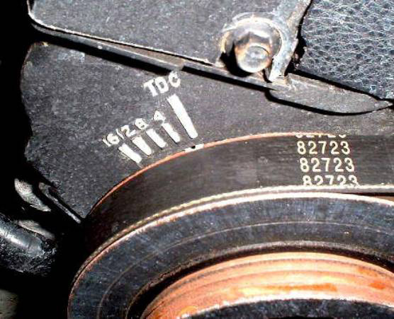
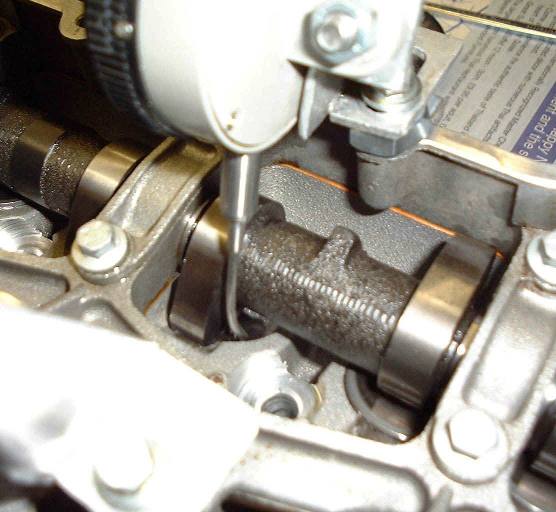
are fitted it is necessary to establish TDC for cylinders 1 and 4 on the engine, this is
actually marked with a small embossed pattern on the front timing cover and a
corresponding small notch on the back face
of the pulley, it is probably a good idea to mark the embossed line for TDC (this will be
the last line on the right in a group of 4 lines on the cambelt cover) and the notch on
the back of the pulley with a
small dab of white paint or similar to make it easy to spot. The picture below shows the
timing marks with the crank aligned at TDC. This will get you close to actual TDC, the use
of a dial gauge with suitable extension should be used to exactly pinpoint TDC.
To
establish the correct cam timing you will need the equipment described in the second half
of this document, at least a pair of dial gauges, an allen key of the correct size for
your pullies and a 17mm socket and bar, or 17mm ring spanner.
Procedure for inlet valve
i)
Remove the cam cover and gasket
ii)
Remove the cam belt cover
iii)
Turn the engine to exactly TDC (Top dead centre on nos. 1 / 4)
iv)
Select the cylinder that has both valves slightly open (it will be 1 or 4)
v)
Take your dial gauge and clamp it so that the point of the gauge is resting on the cam
follower of one of the inlet valves for the selected cylinder and is perpendicular to the
surface of the follower, it the tip isnt long enough, use a small piece of TIG wire or
similar to extend it,set the dial gauge scale to zero.
vi)
Turn the engine anti-clockwise slowly
until the needle on the dial gauge no longer moves. This indicates that the valve is shut,
note while doing this how much the needle moves, this value is the current lift at TDC,
turn the engine back to TDC and note the movement in the needle to confirm.
vii)
If this is not the desired value, slacken the clamp bolts on the vernier and then using a
long extension bar and a 17mm socket turn the cam using the centre sprocket bolt to change
the lift, if you want more lift, turn the cam sprocket bolt clockwise (so that the vernier
needle moves towards the 'advance' side), if you want less lift turn the cam sprocket bolt
anti-clockwise (towards the 'retard' side). While doing this note the change in lift until
it reaches the desired figure, then tighten the clamp bolts on the vernier.
viii)
Turn the engine back to TDC and then recheck the lift by turning the engine anti-clockwise
and noting the needle movement again as in section vi, re-check by
returning to TDC
ix)
If it's not right, repeat steps vi) to viii)
x)
Attach the dial gauge so that the the tip is resting on a cam follower for one of the
exhaust valves in a similar manner as descirbed in section v, set the
gauge scale to zero.
xi)
Turn the engine clockwise until the
needle on the gauge no longer moves which indicates that the valve is shut, note while
doing this how much the needle moves, this value is the current lift at TDC, turn the
engine back to TDC and note the movement in the needle to confirm.
xii)
If this is not the desired value, slacken the clamp bolts on the vernier and then using a
long extension bar and a 17mm socket turn the cam using the centre sprocket bolt to change
the lift, if you want more lift, turn the cam sprocket bolt anti-clockwise (so that the
vernier needle moves towards the 'retard' side), if you want less lift turn the cam
sprocket bolt clockwise (towards the 'advance' side). While doing this note the change in
lift until it reaches the desired figure, then tighten the clamp bolts on the vernier.
xiii)
Turn the engine back to TDC and then recheck the lift by turning the engine clockwise and
noting the needle movement, re-check by returning to TDC
xiv)
if it's not right, repeat steps xi) to xiii)
It's
easier to do than to type and its intuitive too.
Equipment required
This part of the document describes the equipment necessary to correctly set the cam timing on the Rover K series engine. The bracketry shown can also be used on many other DOHC engines with 20-22 degree valve angles and has been designed to allow use on K16 and also VVC engines (these have a taller cam ladder).
The
primary considerations aretwo dial gauges and some bracketry to fix them to the top of the
cylinder head where![]() they can accurately establish Top Dead Centre on
any cylinder and also give a reading of lift at TDC. The brackets are best made from 2mm
or 2.5mm aluminium.
they can accurately establish Top Dead Centre on
any cylinder and also give a reading of lift at TDC. The brackets are best made from 2mm
or 2.5mm aluminium.
The
best type of gauge used to establish TDC is an analogue one with a radial scale and
rotating needle hand or pointer. This is because at the point of TDC it is easy to spot
when the needle stops moving and then starts to reverse its motion, the dwell point at TDC
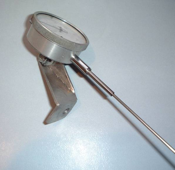
is then easy to determine. A simple bracket is used to mount the analogue gauge above a
plug hole using one of the cam cover bolt holes as a mount. The probe on the analogue
gauge should be unscrewed and replaced with a piece of stainless TIG wire which has been
tapered to allow it to screw hard up into the gauges threaded shaft. The wire must extend
the gauge probe to 172mm from the base of the mounting bracket, this ensures that the
probe will be long enough to reach the piston on both K16 and VVC engines. The design for
the mounting bracket is shown below together with a couple of pictures of the gauge and
bracket as assembled. A cheap but accurate dial gauge can be bought for around �10 from J
& L Industrial supply. Make sure that the one you buy has a mounting lug on the rear
of the casement.
TDC bracket with gauge attached
The
best type of gauge to measure the lift on the valve is a digital type that can be zeroed
and then give an accurate absolute measurement of lift, radial analogue gauges are far
more difficult to read when measuring and adjusting absolute lift. Although digital gauges
are more expensive (around �50 from J & L) they will save time and aid accuracy.
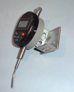
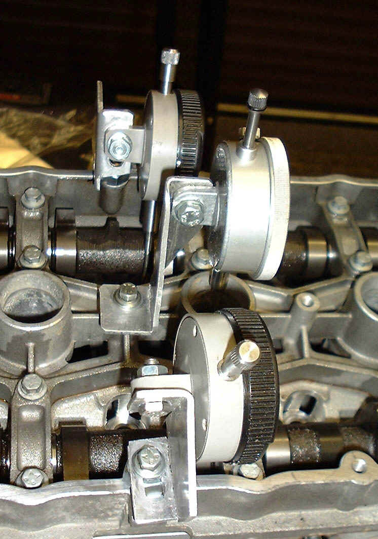
A
simple bracket is used to mount the gauge above the follower at the same angle as the
valve and follower so that it traces and measures lift accurately. When mounted the
gauge’s proximity to the cam requires that the probe at the tip be bent in such a way
as to clear the core of the cam and rest on the top of the follower. The tip of the probe
is again unscrewed from the gauge and replaced with some suitable TIG wire that has been
tapered and screwed into the gauge shaft. This wire is bent as shown in the photo to clear
the cam core. The distance from the base of the mounting to the tip of the probe measured
vertically should be approximately 56mm.
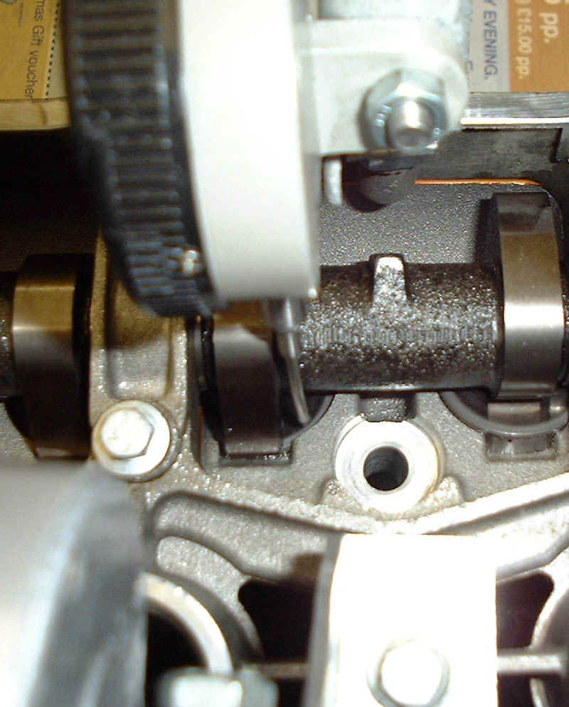
I
use two of the brackets that are mirror images of one another and two digital gauges but
it is possible to use a single bracket and gauge and re-mount the gauge appropriately for
each side. The slots in the brackets ensure that the gauge(s) can be mounted with
sufficient movement in either direction to measure the valve lift and so that they may be
used on K16 and VVC heads. The bracket(s) are mounted on the top of the head using one of
the cam cover bolt holes, the gauge probe is set to touch the top of the rearmost cam
follower for any cylinder just alongside the cam lobe as shown in the photos.
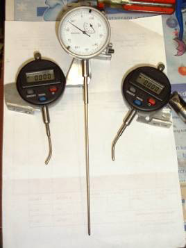
Valve lift gauge attached to bracket All three gauges
Gauges attached to head
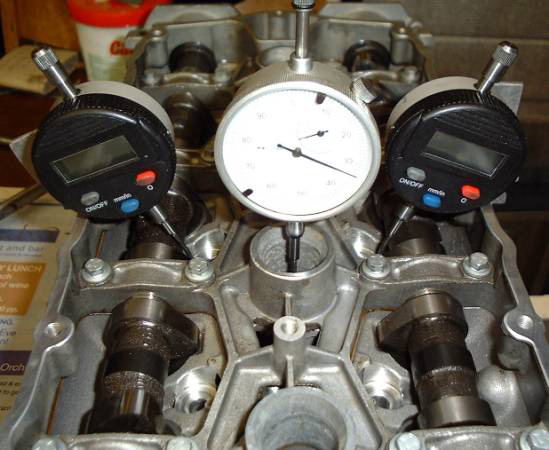
Side view of gauges mounted
Analogue
dial gauge
AMJLP-58005H Metric
9.95
AMJLP-59005C
Imperial
9.95
Mitutoyo
Lift at TDC settings for common cams
| Plenum | in inches | TBs | in inches | |||
| Profile identity | Duration | Lift (mm) | Inlet | Exhaust | Inlet | Exhaust |
| 1369/VVC exhaust/TF135/PTP140 | 252 | 9.32 | .030" | .025" | .035" | .030" |
| BP270 (new) | 260 | 9.65 | .040" | .030" | .050" | .040" |
| 633 | 264 | 10 | .045" | .035" | .060" | .055" |
| 1320 | 268 | 10.6 | .045" | .035" | .070" | .060" |
| Caterham SS | .060" | .045-.050" | .080" | .060-.065" | ||
| BP285H | 274 | 11 | .110" | .095" | ||
| BP285M (740) | 276 | 11.2 | .120" | .100" | ||
| VHPD (827) | 280 | 10.2 | .130" | .115" | ||
| 1227 | 280 | 11.2 | .140" | .125" | ||
| 1444 | 278 | 12 | .140" | .125" | ||
| 2180/1444 | 290 | 12.4 | .160" | .130" |